Well bore schematic drawings show the important ahem bits of an oil drilling system from up on the surface to way down in the Earths crust. The drawing of the well and its equipment showing depths sizes grades and specific equipment.
Solved Draw The Wellbore Schematic And Arrange The Following Chegg Com
UIC Region 5 Created Date.

. The easiest way to create a schematic diagram is to use the pre-drafted designer quality templates available in EdrawMax. SmartDraw is more than just easyit is also an incredibly powerful tool. An unlimited number of diagrams can be created for each well allowing users to retain a fully documented history of each phase of the wells life.
For developingdesigning of a 3D Drilling Well Schematic Im looking for a best solution. Multiple Diagram Versions and Duplication Feature. The Horizontal Borehole Schematic is a data-driven rendering of the borehole.
A Wellbore Diagram must be attached to the Form 2 submitted to deepen re-enter recomplete to a different reservoir or to drill a sidetrack of an existing well. The Reporting Day end is defined by the Reporting Standard. This file is very awesome and helpful to produce high-quality representative drawings for almost all tools during the life cycle of the well.
The schematic is built from the downhole and surface equipment details entered into the database including depths lengths diameters and dates. Here are some 2D painting of the drilling wellbore schematic. Retain Wellbore Diagram History.
Free Wellbore Schematic Excel Template. US EPA Region 5 Office of the Regional Administrator Subject. Well Name and Number ii.
Estimated Injection Rate 100 BWPD 56spm slip speed 86 stroke Maximum Injection Rate 240 BWPD 124spm slip speed 86 stroke Minimum Injection Rate 11 BWPD 15spm slip speed 60 stroke Operating at 24 hours per day. The design of. DGWS Wellbore Schematic Example.
Select one electrical schematic diagram template to edit on it or click the sign to start from scratch. In the well schematic I want to show some pipesflow direction by arrow lines and other objects like bit. My most recent research on the subject came to.
Current and Proposed both diagrams on the. An engineered well and the corresponding completion is the link between the subsurface accumulation of hydrocarbon and the producing surface facilities which deliver the hydrocarbon to market. Select from a huge library of vector schematic diagram symbols that scale easily without quality degradation.
From initial completion to recompletion or a major workover each version captures a snapshot of what the well looked like at the time. You can create graphs showing diagrams of the various aspects of your wellbore from the casings to the packers and tubing all the way down to the perforations. We offer powerdraw Smart Tool Icons in two packages each tailored to your specific needs.
A wellbore diagram should include all permanent downhole features and diagram labels. May 7 2014 By Visio Guy 3 Comments. Therefore if a Drillstring was pulled before the end of the Reporting Day then it will not appear in the schematic.
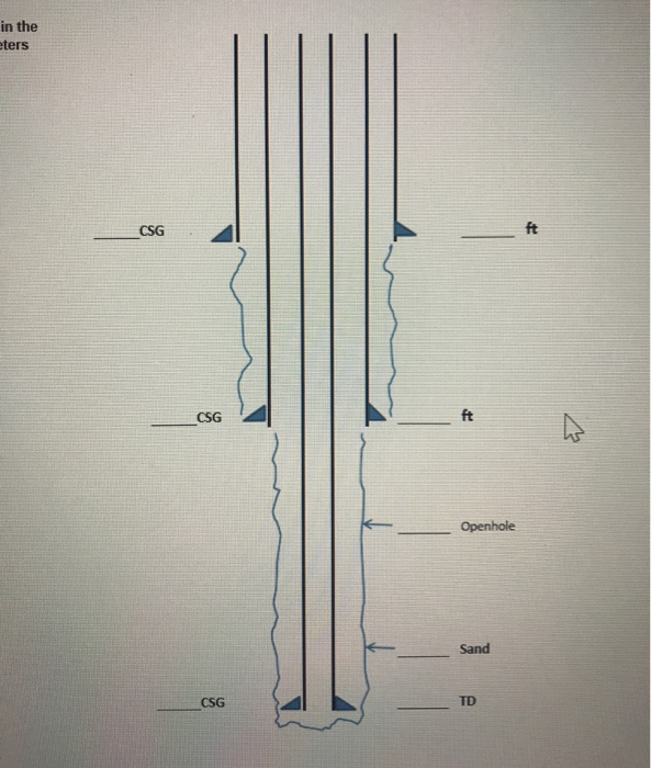
PetroBase WellBore Schematic is a shared application for tracking vital data throughout a wells history. QUESTION 1 Draw the wellbore schematic and arrange the following sequence of events1 thru 20 in the order they would occur when drilling and completing a well. Draw the wellbore schematic and arrange the following sequence of events1 thru 20 in the order they would occur when drilling and completing a well with the following parameters 11 34 Surface Casing set at 500 ft 8 58 32 ft Intermediate Casing Set at 6300 ft 4 12 135ft P-110 Production Casing set at 11600 ft Fracture Gradient 0770 psift Pore.
For years Ive been toying with the idea of creating a set of shapes for well bore diagrams. Ive been searching for a while to find a simple excel spreadsheet or similar that can draw up your well schematic for you. Drilling with Visio.
9242018 83439 AM. With high quality accurate well schematic drawings. Wellbore Schematic Diagram Author.
They are particularly useful for viewing during permit review changes of well configuration and when determining plugging requirements. The Wellbore Diagram Tool draws well configuration and geology for easy interpretation by agency users. Table of Contents.
Figure A is a schematic flow diagram of cement-slurry preparation that indicates the steps performed at the central storage location and at the wellsite. Also I like to give animation to some of the objects like bit. It includes thousands of templates and examples to help you get started quickly.
Navigate to New Electrical Engineering Basic Electrical Step 3. Construct powerful wellbore schematics scaled from key entries such as completion intervals casing setting depths cement parameters tubing data remedial cement squeezes fluid levels and other downhole information. Using affordable quick and easy-to-use software and services.
I am currently working on Well Plugging and Abandonment approvals for a number of wells and want to be able to produce a simple schematic for each. With our wellbore schematic software visualizing your data is easy. A noteworthy feature in WellView is the drawn-from-data schematic.
When generating a Wellbore Schematic in OpenWells software the schematic is drawn based on the data existing at the end of the Reporting Day. No luck so far so hopefully someone can point me in the right direction. P2s Wellcore Horizontal Wellbore Schematic is a wellbore diagram tool that accurately depicts wellbore geometry and borehole equipment over the full well life-cycle from spud to abandonment relying on existing drilling and completion data capture to drive the wellbore schematic.
The schematic is integrated with. Bottom Hole Assembly BHA Components and Design. SmartDraws schematic diagram software is easy to use.
You can create clean concise and precise graphs detailing every aspect of the well completion. Create complex well geometries while designing completions with devices and valves best suited for a variety of phase control scenarios. Fields used to draw the Wellbore Schematic.
These diagrams facilitate assessment and understanding of wellbore configurations and potential risks. One Source For Viewing Downhole Data. These templates are free to use and customize and you can take them as a foundation for your diagram and edit it to develop a version according to your requirements.
Run Openhole logs to determine reservoir properties Run production casing to Total Depth - - Set Final Wellhead assembly Displace Production casing Top plug and cement volume with. We help oil gas workers around the world to visualize their wells. The result is a visual overview of each well with a myriad of options to customize the display.
Download now free wellbore schematic excel template which contains drawings and tally templates for almost all tools required for drilling completion workover operations.
Do You Know How The Wellbore Schematics Diagrams Evolved From Lines And Boxes Drawn By Hand To Computer Generated Icons

Schematic Diagram Of A Single Gas Lift Oil Well Download Scientific Diagram
Free Wellbore Schematic Excel Template Drilling Manual

Do You Know How The Wellbore Schematics Diagrams Evolved From Lines And Boxes Drawn By Hand To Computer Generated Icons

Shows A Schematic Diagram Of Drilling Fluid Circulation During The Download Scientific Diagram

Free Wellbore Schematic Excel Template Excel Templates Templates Excel
Free Wellbore Schematic Excel Template Drilling Manual

Schematic Diagram Of Typical Well Design Showing A Structure Of An Download Scientific Diagram
0 comments
Post a Comment